OK so let’s move on with a list of materials. The list below is to construct a jig with the same dimensions and appointments as my own. However nothing is too critical and you may need to alter some things along the way to better fit your own bandsaw. All these measurements are of course determined by the location of the mitre slot in your bandsaws table or auxiliary table. The idea then is to have the Sub-base wide enough so that when the jig is in operation, the long "indexing arm" can be align to make contact with the actuation "Striker", which is clamped to the outboard edge of your bandsaws table, the base extends inboard thereafter to where the blade makes entry into the jig and then further inboard again by about 2 1/2" to accommodate the out feed "guide" block which, on my jig, overhangs the inboard end of the Sub-base. As a note, the Sub-base on my jig overhangs the outer edge of my bandsaws table by 1".
So you should now have some idea just how wide your sub-base needs to be, if so, your in business. Simply adjust the cut length of the Lexan "Face Plate" to match your Sub-base and cut the rest of the Lexan components to plan. Don’t be too concerned at this stage with any other alterations that may be needed, these should become more clear as you progress along. Just remember that we are not talking a great deal of material here, if at any time you find yourself having trouble following my instructions, or maybe getting a little baffled by any detail, just take what you can from this guide and try to proceed via trial and error, the basic function always remains the same, as long as you can cut your own kerfing at the end, who cares how you get there.
An Alteration Note
From his instructions, it would appear that Daniel chose to use 3/16" Lexan for all components accepting the shortest "Indexing Arm". Which because of the requirement to drill through it's thickness to accommodate the "Indexing Pin", which in operation needs to make contact with the stock fairly low down, 3/8" material was chosen for this component. In the interest of rigidity, (and this is probably unnecessary) but in the main to allow fitment of brass bushings to all pivot points, I decided to beef up all Lexan components aside from the 4" x 4" base, the "Face Plate", and the "Holder for Strip Guide" to 3/8" material. I will provide more information on these very simple yet affective bushings later in this post.
The Materials List
1 x 9 ?” x 5 ?” rectangle of ?” ply (Sub-Base)
1 x 9 ?” x 4” rectangle of 3/4” ply (Indexing Base)
1 x 11" length of metal or hardwood the slides freely but without side play in the mitre slot of your own bandsaws table
1 small off cut from a 3/16" thick sheet of Lexan app 10" x 5"
1 small off cut from a 3/8" thick sheet of Lexan app 8" x 3"
2 curtain hooks or other apparatus to connect the spring or rubber bands to.
1 x big thick industrial sewing machine needle or other hard metal pin that can be sharpened to a chisel point. (maybe a small Allen key or drill bit)
3" x 1/4" threaded rod.
2 x 1/4" T-nuts
3 x 1/4" Nylok nuts
1 x 1 1/4" x 1/4" cup head bolt
1 x 1" x 1/4" countersunk machine screw (with flat washer)
1 x 1 1/4" x 1/4" machine head bolt with washer
4 x thin fibre washers to fit the 1/4" threaded rod
1 x short length of brass tubing 9/32" OD (I got mine from Bunnings (think home depot) you could also try a hobby shop)
I will leave you to work out the number and size of practical board screws that you will require to fix the various components together. Just remember two things, for smooth operation, all screws must be counter sunk flush with or just below the surface of the Lexan and mitre bar and don't use screws so long that they will come through the other side of the jig even just a little.
Building the KSled
Well, now that you have had a look at Daniels instructions and you have a materials list lets move on. By now you should have your materials worked out and your 3/4 ply Indexing Base should be cut to exactly the same width as your Sub-base. We now need to rebate this 3/4" ply "Indexing Base" so that it will accept the 4" x 4" piece of 3/16" Lexan from the cut plan flush with the surface of the ply base as shown in the images below. But before we can do this, we must first determine just where on the "Indexing Base" this rebate needs to be.
Let's look carefully at the very first image of the jig above, note the angle of the "Long Indexing Arm". In this image the arm is positioned after having already made contact with the "Striker", but the blade has not yet cut the kerf in the stock. See how the end of the "Long Indexing Arm" is now free to ride on the flat parallel SIDE of the "Striker" with no further inward movement. You can see the angle that the "Long Indexing Arm" would have occupied while at rest before it made contact with the angled face of the "Striker" by observing the gap between it and the Lexan "Stop" block to it's right, on my jig this angle is about 10 degree. However the exact angle is not that critical just as long as some outward angle has been built in.
Just to be clear, the point is that we want the long "Indexing Arm" to lay out angled away from the blade of the saw a little so that as the end of the "Indexing Arm", makes contact with the angled face of the "Striker", it is pushed inward by that angled face thereby allowing the "Short Indexing Arm" and the "Indexing Pin" to slide the stock to be kerfed across the "Face Plate. And then, BEFORE the actual cut commences, we want the sideways movement of the stock to cease as the "Long Indexing Arm" ride smooth and freely down the parallel side of the "Striker". If this outward angle where to be too slight or negative, the index arm would continue to be pushed inward binding upon the "Striker" whilst continuing to push the stock sideways during the cut thereby causing very stiff operation and a curve to the kerf.
With the above in mind, to determine the position of the rebate in the "Indexing Base", I stacked it on top of the "Sub-base" and placed them on my bandsaws table as if the jig were in operational position. I made up an angled "Striker" and clamped it to the edge of the table and placed the "Long Indexing Arm" in the approximate position to give it the side movement and slide as described above. I then marked the base at a point that would identify the centre of the hole to be drilled that would eventually accept the bolt to secure the "Long Indexing Arm" to the "Indexing Base". Using this mark, I then determined the position of the 4" x 4" x 3/16" Lexan plate.
Daniels "Lexan Cut Plan" has dots marking the position upon this 4" x 4" x 3/16" Lexan plate where holes will be drilled to fasten the various components. I did not use these because I'm and idiot and did not look, but I am sure you could. Anyhow, now that you have marked the position of one of these dots on your "Indexing Base", I guess you can now go ahead and use Daniels plan to determine where you should mark out your rebate.
Phew! I hope this is making some sense folks, if your finding it hard to read, you should try writing this stuff. On the brighter side, if you have made it this far you are over the worst of it, the rest is pretty straight forward. Here are some images of the rebate in the "Indexing Base". Because it is so easy to set-up, I used my tablesaw like a dado with the blade wound up 3/16" to accept the Lexan. Mark your "Indexing Base" and go at it with the mitre guide.
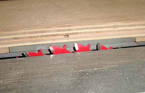
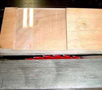
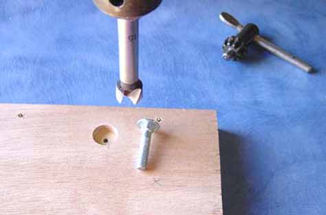
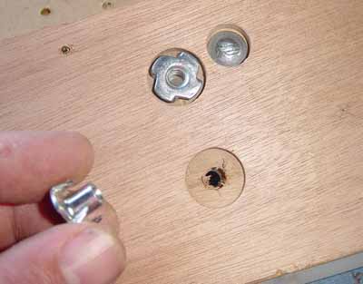
You can now go ahead carefully drilling and countersinking the 4 holes in each corner of the 4" x 4" Lexan plate and then fastening it in position using short 20mm/ 3/4" particleboard screws. These short screws will be removed later and longer screws will replace them to fasten the 2 bases together. But for now, 20mm is good, DO NOT drill any other holes in the Lexan until the plate is fastened. Now that the Lexan plate is secure, you can go ahead and drill a SMALL PILOT HOLE through the Lexan and right through the 3/4 ply to mark the position for each of the 1/4" bolts that will secure the "Long Indexing Arm" and the "Spacing Adjustment" piece. When done, you can flip the "Indexing Base" over and using the pilot holes as a guide for a Fostner or spade bit of suitable size, you can then rebate the underside of the base to accept flush or below the base the "1/4" Cup head Bolt" which will fasten the "Long Indexing Arm" and the "2 x 1/4" T-Nuts" that will secure the "Spacing Adjustment" piece.
Once these rebates have been made, you can flip the "Indexing Base" back over and graduate the holes out to 1/4" right through the Lexan and the ply, flip the base back over and shallow drill the 1/4" "T-Nut" holes to accept the "T-Nut" thread shaft. You can now fit the "T-Nuts" and the "Cup Head Bolt" into position. But, if your bolts are too long, you may need to trim them to length so they do not protrude through the base when in position on the Lexan components.
Next drill (in safe increments) all the 3/8" Lexan components, (accepting the "Stop Block" which is drilled and countersunk to accept particleboard screws only) out to 1/4" and then, at the pivot points being each end of the "Long Indexing Arm" and the rounded end of the "Short Indexing Arm", out to 9/32" . But what about that brass tubing? Well if you did not get any it does not realy matter too much, you can use other fasteners for the pivot points and forget about the 1/4" bolts (you did of course read this far like I warned before you drilled didn't you) this is just my own modification. As far as I am aware, neither Daniel or Frank uses this method on their jigs but I found it to be pretty slick.
As mentioned ealier, I use brass tubing to make very simple and effective press fit bushings for the pivot points in the Lexan, it makes things run very smooth and accurate. I guess some of you may be across this method already but I discovered it myself some time back and have found it extremely useful for all kinds of things so keep this tip in mind, it will come in handy down the track for other projects I'm sure. The next image shows some of the brass tubing and a 9/32" drill bit that provides the perfect bore for a gentle push fit of the brass bushing.
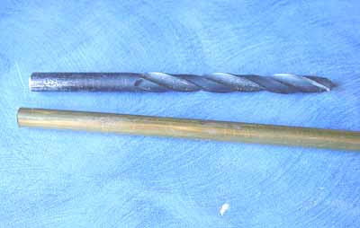
Once you have drilled your Lexan (clamped securely and in safe increments) out to 9/32" you simply use your bandsaw with that fine tooth metal blade, to cut a small piece of the brass tubing just a tiny bit shorter than the lexan is thick. Gently clean off the burr from your little brass bushing with a fine needle file (not too much now, we want a press fit), and press it home into the hole you drilled in the Lexan. This piece is now ready to accept a 1/4" bolt or threaded rod as a shaft.
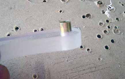
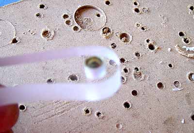
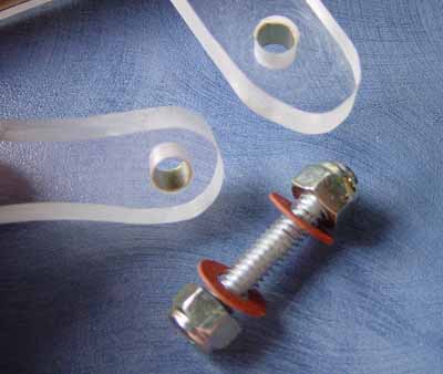
Here is the configuration that I used to link the 2 "Indexing Arms". The fibre washers go directly below the "Nylok Nuts" on the surface of the Lexan, and then they are nipped up snug and backed off a little to obtain the desired freedom of movement. Same goes for the lower end of the "Long Indexing Arm". I used the 1/4" machine screw to fasten the upper part of the adjuster, and a 1/4" machine head bolt with fibre washer and metal washer on top for the lower sliding part of the adjuster. The adjuster slot is made by drilling a 1/4" hole in the adjuster material about 2/3rds the way across in line with the bolt shaft. You then cut either side of the hole with a fine tooth saw and file the slot clean. Note that the top screw of the "Stop" is fixed into the same hole that was drilled in the 4" x 4" Lexan plate.
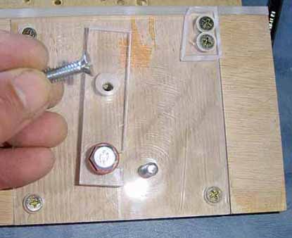
Now here is where Daniel informs me that he made an upgrade to his jig and you can see that same alteration in my own effort. If you look closely at Daniels tutorial, you will see that the angle of attack that the "Indexing Pin" makes when in contact with the stock is quite acute. This steep angle tends to push the stock more firmly against the "Face Plate" than is necessary so rather than just sliding the stock along, it introduces a tendency for the indexing pin to dig into the stock itself. This not only causes a less fluid operation of the jig but also it can cause the stock to be dragged back across the "Face Plate" as the jig is retracted past the "Striker"
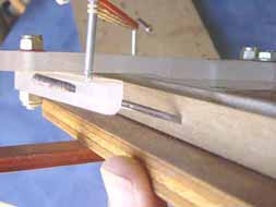
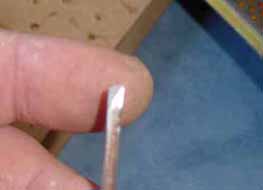
As mentioned in my "List of Materials" I have used an industrial sewing machine needle for the indexing pin on my jig but any hard steel pin could be used. Maybe an Allen Key or a drill bit will do so long as it can be sharpened to a chisel point as recommended by Frank Ford it will be fine. When first set-up, I has drilled the hole for this needle on a horizontal plane through the end of the "Small Indexing Arm", this was a mistake as the pin made contact with the stock too high up. The main problem was that when kerfing pre-radiused stock for reverse kerfing, I was forced to cut with the radius part of the stock toward the base of the jig, this gave a bit of fuzz on the visible radius when done. Drilling at an angle through the "Small Indexing Arm" to accommodate the "Indexing Pin" has addressed this issue and now my kerfing is much cleaner than I showed in my initial post way back when I first mentioned this jig.
This next set of images attempts to show the more gentle angle of attack that "Indexing Needle" makes with the stock on my jig. The angle of hole that was drilled in the "Small Indexing Arm" to accept the "Indexing Pin". And how the needle was sharpened to a skew to counter that angle and allow full contact.
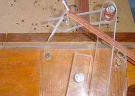
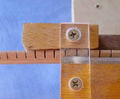
Daniel also mentioned that he made another up grade to prevent the stock from back feeding and I will include those details at the bottom of this post. As you will see in the image below, when I put my jig together, I extended the "Guide" block past the inboard end and shaped it with a curve so the stock would be inclined to feed back and angle away from the neck of my small bandsaw. Being that it is fastened with only one screw through the "Holder for Strip Guide" piece of Lexan, I have found this block to be handy as it pivots. Because of the shape it's adjustability it affords just enough friction to mostly eliminate the backfeed issue. I also do not mind holding the stock with my finger in rhythm with the feed, but if you were doing a lot of this I am sure there is a better way. For now this will do me.
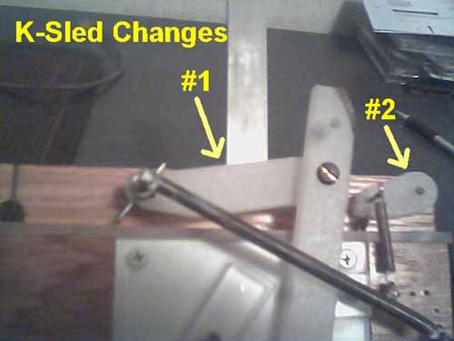
And here we have Daniels anti backfeed update that I recieved from him after I done up the original version of this tutorial:
#1 is just how I changed the angle of the index arm. #2 is the little arm I added to stop the strip from being pulled backward.
Now all that you need to do is fit some kind of hooks to hold the rubber bands or spring in place, fit the "Stop" block, and the "Strip Guide Holder" align the jig back onto your bandsaws table checking all is in order and finally fit the mitre bar to the Sub-base , change out the small 20mm particle board screws that were holding the 4" x 4" Lexan plate to the Indexing Base so that all is secure, dimension down some stock and cut some kerfing.
If I have forgotten anything, I am sure you will all let me know
Cheers All, hope this helps someone, and Happy Kerfing
Kim


